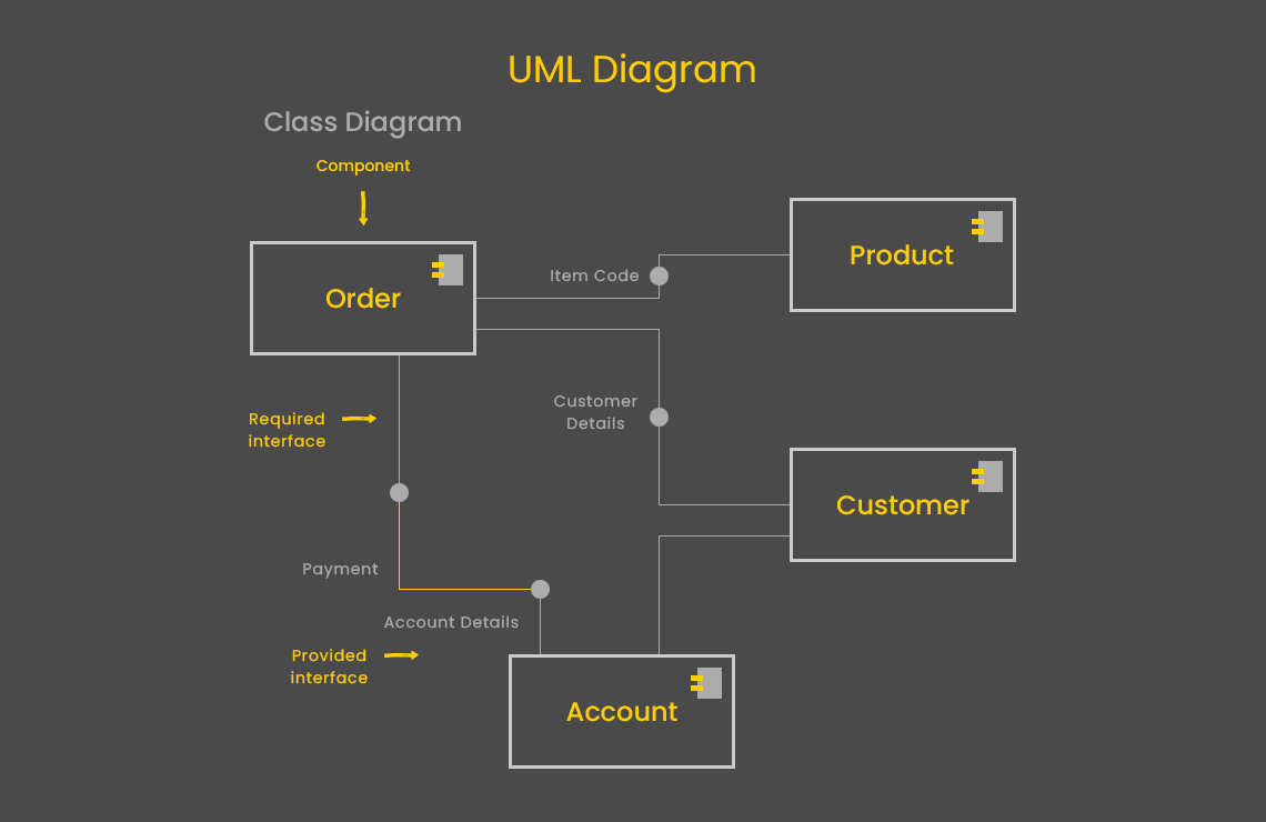
UML Diagram & its Types – All You Need to Know
Where wireframes represent essential elements of a product, a mockup can help you visualize it before it’s even designed. It represents its structure and shows how it will look before development.
But, there is something else that is more complete. Something that is rich; that can effectively represent application structures, system behaviors, and business processes. It is called nothing else but a UML diagram.
UML Diagram is regarded as a standard system for software development modeling by Object Management Group (OMG). The core purpose of this format is to highlight the progress, spot the errors, and analyze the ongoing workflows. All this is entirely based on the collection of diagrams, which are tasked to visualize the different functions of software development.
What is a UML Diagram?
UML Diagram is the blueprint or the layout of a software process – it gives a visual presentation of the entire function or specific phases. It is known for establishing the object-oriented model views of intricate software development and engineering processes by utilizing real-world entities. Therefore, the diagrams based on this idea offer clear picturesque to even the non-technical end-users as well.
This visual presentation uses object-oriented languages such as Java and C++ to establish a meaningful and in-depth view of the technical process. Unlike the website and app modelling structures, this one is carried out by adept developers instead of UI experts. At the same time, it is designed to keep business executives, other company-wide departments and end-users in the loop.
UML isn’t limited to a specific diagram type or software phase. It has around a dozen types to acquire the entire software development and solution processes.
Types of UML Diagram
So, what are the different types of a UML diagram? A UML Diagram is divided into 2 types:
- Structural Diagrams
- Behavioral Diagrams
These are further categorized as follows:
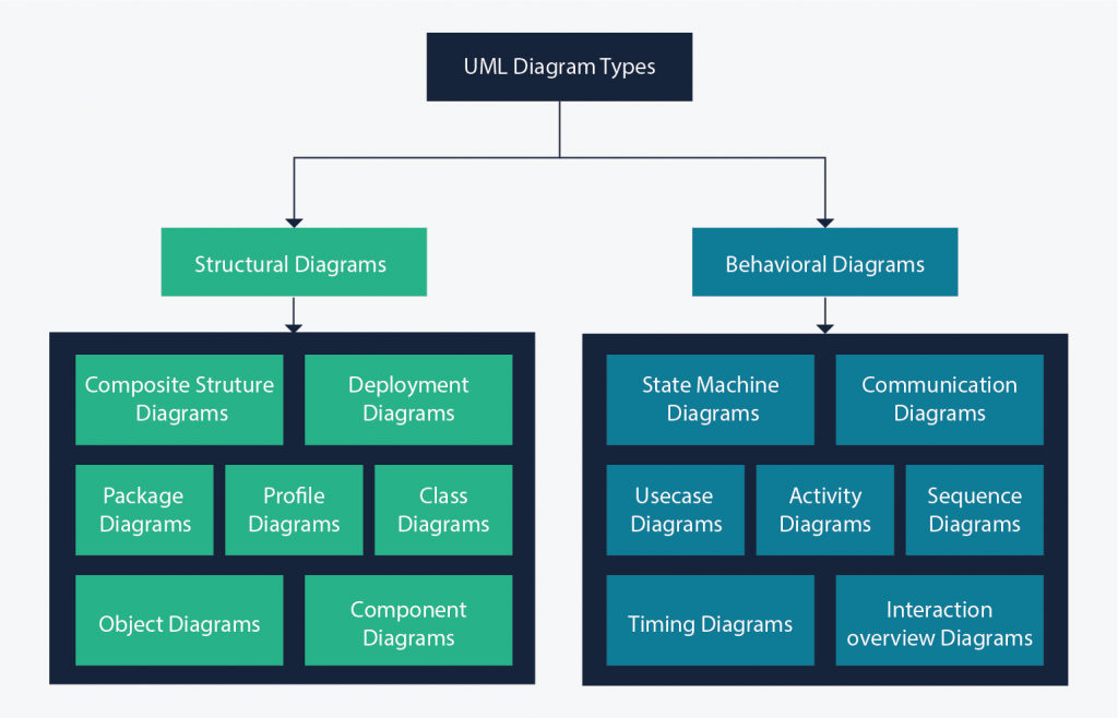
Structural Diagrams
- Composite Structure Diagrams
- Deployment Diagrams
- Class Diagrams
- Profile Diagrams
- Package Diagrams
- Component Diagrams
- Object Diagrams
Behavioral Diagrams
- Sequence Diagrams
- Activity Diagrams
- State Machine Diagrams
- Communication Diagrams
- Use Case Diagrams
- Timing Diagrams
- Interaction Overview Diagrams
Structural Diagrams
Composite Structure Diagrams:
It highlights internal structure and relationships between different classes in the function.

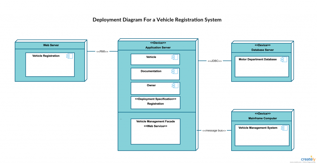
Deployment Diagrams:
This diagram showcases hardware resources in the process including different components and nodes.
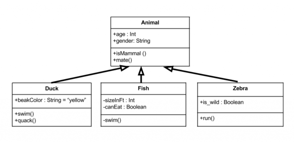
Class Diagrams:
Class Diagrams focus on representing three main elements: attributes, behavior, and names.
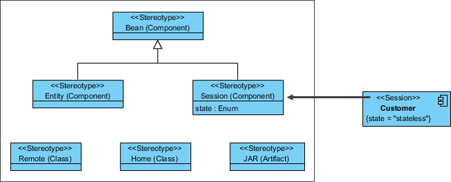
Profile Diagrams:
Profile Diagram rolls out as part of UML 2.0, which takes care of the entire meta-structure of the software.
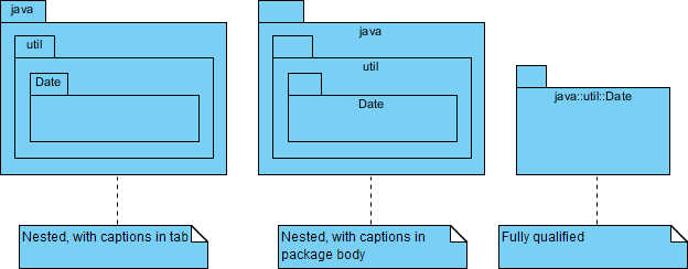
Package Diagrams:
As a subset of class diagrams, package diagrams places elements of a system into relevant groups to minimize the group dependencies.
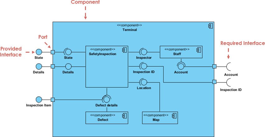
Component Diagrams:
As the name suggests, it revolves around simpler components and their dependencies on one and another.
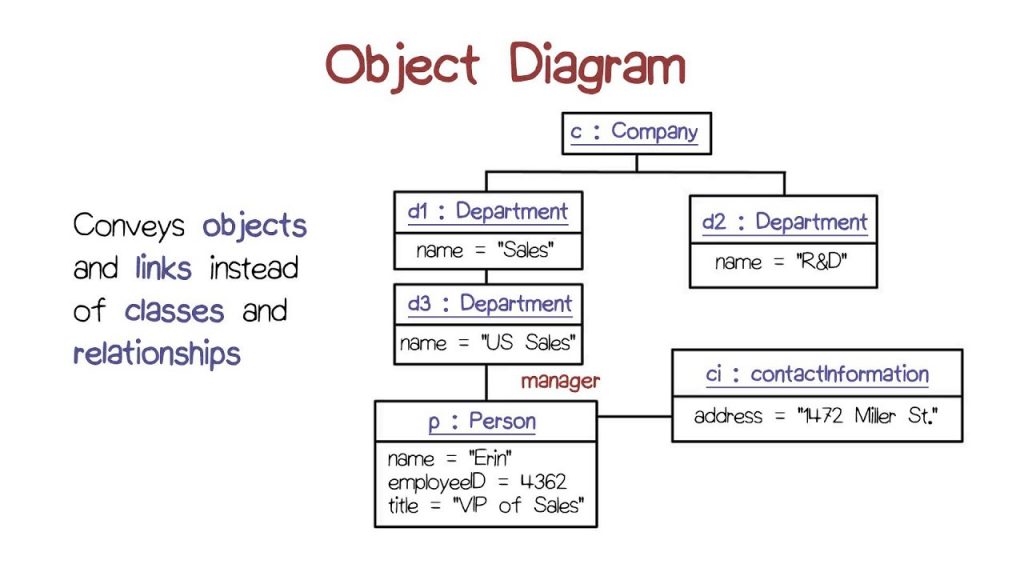
Object Diagrams:
It’s quite similar to class diagrams. Unlike class diagrams, object diagrams avail real-life examples that showcase the relationship between different objects.
Behavioral Diagrams
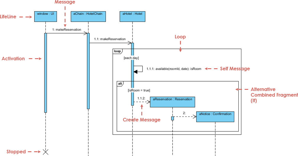
Sequence Diagrams:
This type of UML diagram represents the sequence of the interactions and the messages carried out of them.
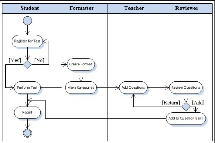
Activity Diagrams:
It represents the dynamic nature of the workflows in a graphical presentation.
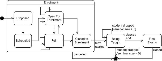
State Machine Diagrams:
State Machine Diagrams revolves around the dynamic nature and actions of the objects in the system.
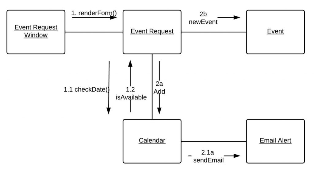
Communication Diagrams:
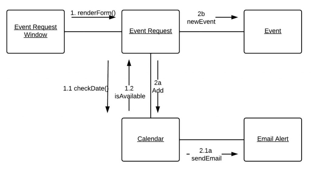
Aka Collaborative Diagram, Communication Diagram throws light on both the static and dynamic interactions of the objects.
Use Case Diagrams:
This diagram features different actors to showcase the functions to the end-users.
Timing Diagrams:
Somewhat similar to sequence diagrams, timing diagrams focus on different functions to be performed within the allotted time.

Interaction Overview Diagrams:
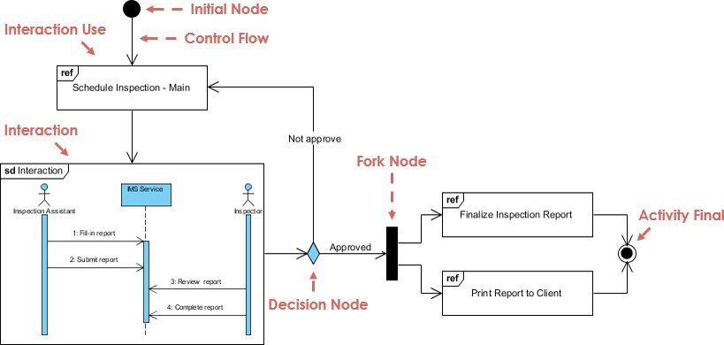
It gives an overview of the interaction diagrams with standing out as a combo of the sequence and activity diagrams.
Conclusion
UML Diagrams and its types are the easiest way to analyze the software development process and then suggest a tentative release date. Not only this, but it also helps in identifying the real-time errors without any lag. If you need to track your software development process, hire a User Interface (UI) developer for the purpose.
